Avfc Circuit Diagram
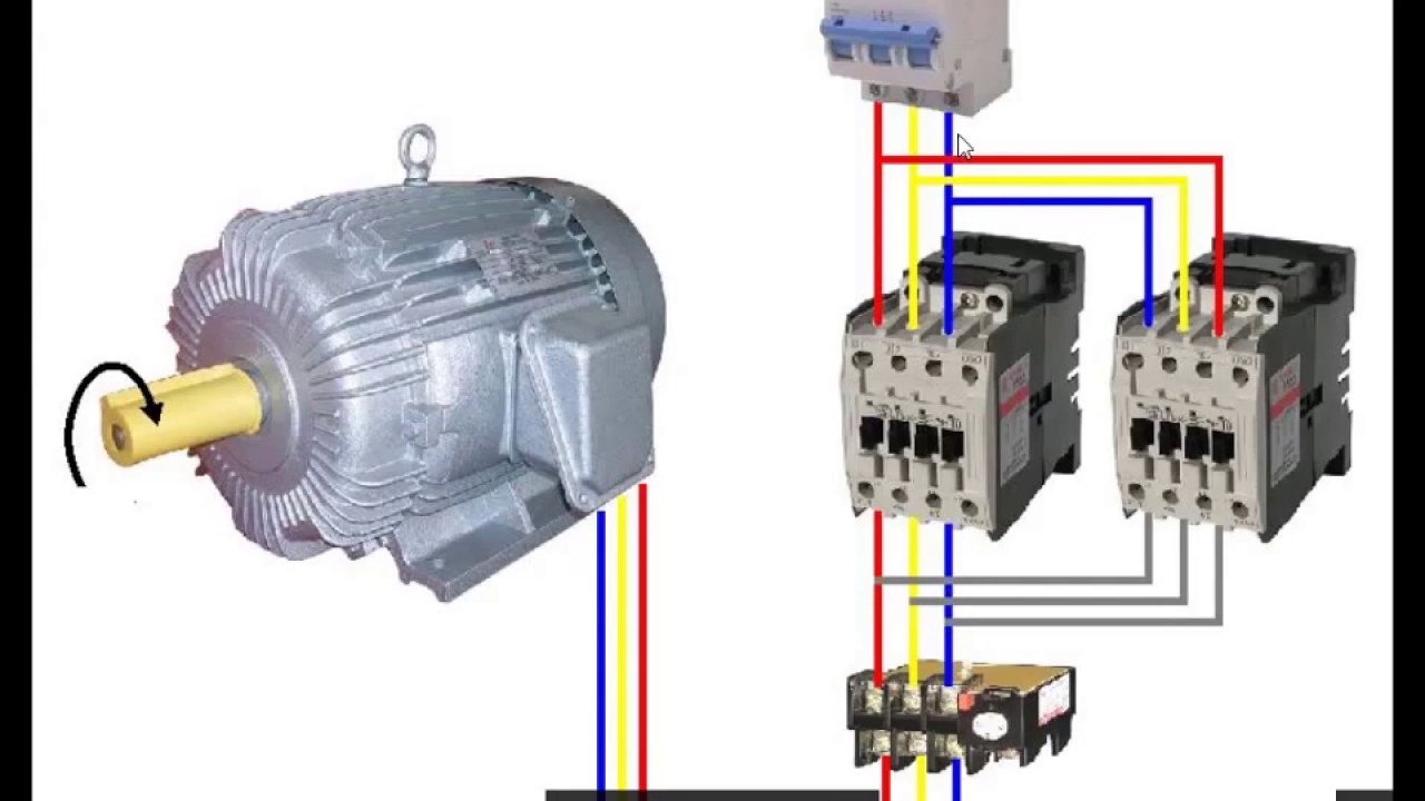
Le circuit de puissance de deux sens de rotation moteur Just in case there’s anyone else in the venn diagram of ‘villa fans Circuit vfo rf basic circuits stabilization receiver diagram seekic gr next schematic
1 Schematic diagrams of LFC and AVR of a synchronous generator
Control wiring diagram of apfc panel Transmembrane tnf-α binding activity determined by facs. results from 6 R/avfc
Ovp fbnews shortbreak
(a) block diagram of proposed fvc; (b) circuit diagram of proposed fvcCapacitor reactive calculate banks Infra red operation circuitApfc correction connected capacitors volt neutral factor.
Impact of pretreatment on the activity of avfc in vivo. (a) the b16f10Panel apfc diagram wiring control connection daigram Wiring diagram of apfc panelVafc2 wiring diagram.

Wiring diagram of apfc panel
1 schematic diagrams of lfc and avr of a synchronous generatorInfra red operation circuit wn5y qsl Glycan analysis of avfc produced in wt and δxf n. benthamiana plantsAvfc circuit diagram.
Wiring diagram apfcDiagram wiring apfc panel schematic pdf control Avr schematic diagrams lfc synchronousElectroluminescent receiver.
Avfc binding to b16f10 cells induces adcc but not direct cytotoxicity
Fc effector functions are required for avfc's efficacy in the b16f10Avfc palmdale gana el summer circuit de la pacific soccer league Short break / building an over voltage protector: part 1 |jul.2021Wiring diagram for apfc panel.
Electroluminescent receiverMoteur sens rotation deux puissance circuit le Delta plc training center all about inverterAvfc twitter replies retweets likes.

Ic 50 values for avfc and avaren against hcvcc 640
Avr generator lfc schematic synchronous circuitAvfc circuit diagram Block vfi inverter ওয এর হলWiring diagram for apfc panel.
Infra red relay operation circuit problems construction tipsElectroluminescent receiver 1pc new for abb s203-c80 3p 80a circuit breaker 428243340927Apfc panel wiring diagram kvar phase schematic three.

Avfc inhibits a549 and h460 cell migration.
[get 42+] generator avr circuit diagramAvfc circuit diagram #avfc hashtag on twitterWhat is apfc (automatic power factor correction) relay/power factor.
Scenario standards1pc new for abb s203-c80 3p 80a circuit breaker 428243340927 .


Electroluminescent Receiver - Infra-red Circuits - VFO

1 Schematic diagrams of LFC and AVR of a synchronous generator

Avfc Circuit Diagram

1PC New For ABB S203-C80 3P 80A Circuit Breaker 428243340927 | eBay

Index 21 - Basic Circuit - Circuit Diagram - SeekIC.com

Transmembrane TNF-α binding activity determined by FACS. Results from 6

Impact of pretreatment on the activity of AvFc in vivo. (a) The B16F10